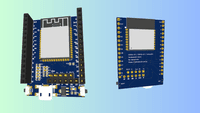
ESP32-S3-WROOM-1, ESP32-C3-WROOM-2 and ATTinyXX4 – 3 in one development board
Here is a custom-designed 3-in-one development board that I recently designed.
The board supports any of the 3 MCUs, Also ESP32 should work but the pinouts will be different. The board includes a 3.3v LDO regulator, and USB micro, with native USB for ESP32s. Pinout for UART as well as UPDI for ATTiny. Two headers for GPIOs and Ground and VCC on each. One extra header with Gnd and VCC on the bottom with remaining GPIOs. There are GPIO0 and RESET buttons on board for booting the ESP32 in Programming mode. The RESET button also works for the ATTiny.
In addition to that, the USB is connected to the ESP’s native USB pins so there is no need for an external programmer needed for ESP32s although you can use the PRG header to program it using external USB to TTL programmers if you need to. The prog header can be used to program ATTiny using UDPI.

Dimensions
- Height: 45.11 mm
- Width: 31.5 mm

The PCB design has been penalized so each 100mm x 100mm panel will have 6 boards in total so 30 PCBs in total will be delivered.
After ordering the PCB, it arrived within a week. They look nice, very ordinary-looking dev boards, except for it support all different microcontrollers 😀

Tiny problem though was I did not recheck the footprint for the USB connector. The pads did not match the connector I had. So I had to do a little adjustment. In below picture you can see the two pads behind is not connected to anything, there were supposed to be legs from the enclosure that should have came in contact with those pads.

Any way by bending the front leg a bit I was able to solder two enclosure legs to the big pads in the front with lots of solder and it stood nice and steady. I could use more solder to solder the back pads with the enclosure directly, but did not seem that I needed to as it was already steady enough.

I decided to use ESP32-S3 first to build my first custom development board.
Soldering 0603 SMD components to a PCB turns out to be more difficult than it seems. Few challenges I had were, right type of flux, and soldering iron tip. I have no difficulty what so ever soldering a big chip like ESP32 because it is stable once you solder 2 pads. The smaller components like capacitors, keep jumping around and my hands are not specifically steady at all. Never realised it. So, after this experience I think I will stick with hot plate reflow or air gun instead. After soldering all the components, it was exciting to test if it actually works, and why would it not work 😀
Check out my short 1-minute video on YouTube about the process of getting PCB delivered to soldering components and then running a blink sketch on an ESP32-S3.
https://youtube.com/shorts/S1Vu47wp1bk

Here is the picture of the board after soldering all the components and a header on the left.

It was really satisfying to see the thing work at the end but honestly soldering those tiny 0603 components, especially the capacitors was not fun. I will try a hot plate for my next one which will be an ESP32-C3 based.
Anyway to show that it actually worked I used a Gyroscope/Accelerometer sensor module and made a BLE Airmouse which functions very well.
Watch the youtube video made while playing tic tac toe with the Bluetooth Low Energy (BLE) Airmouse I created with this module using a Gyroscope sensor.
I will be using this board for more projects, to stay tuned, please subscribe to my Youtube channel.