

Accelerometer / Gyroscope sensor MPU6050 Airmouse with ESP32 x BLE Mouse
I had the MPU6050 module on my shelf for a long time before I finally decided to open it. I was really excited to do an Airmouse project with ESP32 but procrastination has been my friend for all this time. I finally decided to open the static safe seal and solder the header pins to the module board.
I will start with the project in several steps.
- Use Adafruit Library for the sensor and do a simple serial logging
- Use it with my Paint app that uses dual-axis analog joystick in a labyrinth mode ;).
- Modify it to work like more an air mouse rather than a labyrinth
- Use it with BLE Mouse
- Use it with FreeTouchDeck to add air mouse feature to the project
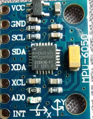
First of all here is how the module looks like.
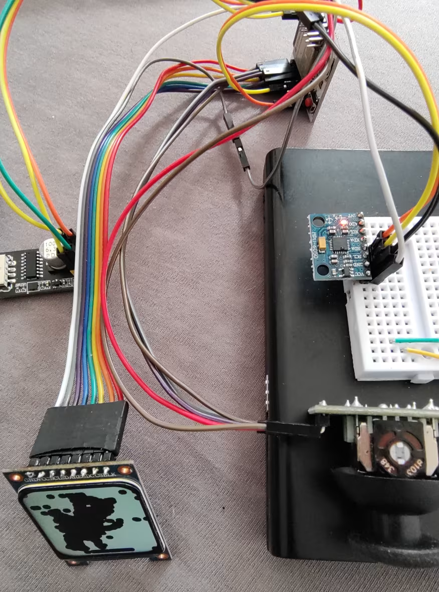
Connected to my Paint project
Use Adafruit Library for the sensor and do a simple serial logging
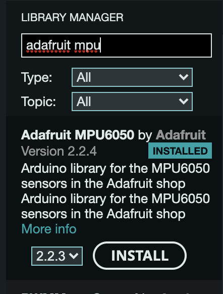
First of all we will use Adafruit library for MPU-6050
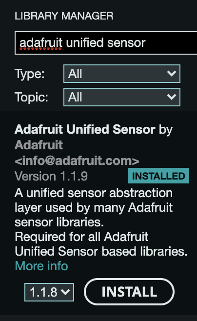
And Adafruit’s unified sensor library
With these Libraries installed, we are ready to read some sensor data. The MPU6050 module uses an I2C interface to talk to the MCU so first of all find the I2C address for the sensor. This can be simply done by searching on Google or looking at the datasheet. 0x68 says Google. And the second thing is which pins to connect the sensor module to.
I2C uses an SCL or clock line and an SDA a data line. For ESP32 we could use any pins to interface an I2C peripheral. I used 20 and 21. Note that 20 is used for USB so be sure you are not using USB at the same time. I am using UART to upload the sketch and serial communication so I used it, so to be safe find a pin that works for you.
With all that ready, we are ready to write some code. I used “Simple Reading” Example form Adafruit’s Library It prints out all the info during the setup and reads and prints out different values to Serial.
#include <Adafruit_MPU6050.h>
#define I2C_SDA 21
#define I2C_SCL 20
TwoWire I2Cax = TwoWire(0);
Adafruit_MPU6050 mpu;

void setup() {
Serial.println("Adafruit MPU6050 test!");
  I2Cax.begin(I2C_SDA, I2C_SCL, 100000);
  if (!mpu.begin(0x68, &I2Cax)) {
    Serial.println("Failed to find MPU6050 chip");
    while (1) {
      delay(10);
    }
  }
  Serial.println("MPU6050 Found!");
}

void loop() {
  Serial.print(" X: ");
  Serial.print(a.acceleration.x);
  Serial.print(", Y: ");
  Serial.print(a.acceleration.y);
  Serial.print(", Z: ");
  Serial.print(a.acceleration.z);
}
Acceleration X: 0.11, Y: 0.03, Z: 10.40 m/s^2The code works, it seems to log X and Y values in a range of -10 to 10 for me. That is a nice base to start.
The second step was
Use it with my Paint app that uses a dual-axis analog joystick in labyrinth mode 😉
You can visit my Paint App blog post to see the code I used there, but to add the accelerometer input to it I simply added a flag that would switch to an accelerometer instead of a joystick to move the cursor to paint, and then if the flag is true, I replaced xValue and yValue with the acceleration value read from the MPU module.
  if (accelerometer) {
    /* Get new sensor events with the readings */
    sensors_event_t a, g, temp;
    mpu.getEvent(&a, &g, &temp);

    xValue = int(a.acceleration.z*10);
    yValue = int(a.acceleration.y*10);
  }

  int x = map(xValue, accelerometer ? -50 : 0, accelerometer ? 50 : 4095, 0, w);
  int y = map(yValue, accelerometer ? 50 : 0, accelerometer ? -50 : 4095, (h - w) / 2, w + (h - w) / 2);

  if (accelerometer)
    tft.fillSmoothCircle(10, 10, 8, TFT_RED, TFT_WHITE);

  tft.fillSmoothCircle(x, y, 8, colors[color], TFT_BLACK);
A red circle will be seen at 10px, 10px coordinate when the accelerometer is enabled.
if (accelerometer)
    tft.fillSmoothCircle(10, 10, 8, TFT_RED, TFT_WHITE);
We multiply the x and y values of the accelerometer by 10 to magnify the data resolution and then cast it to an integer so that we have enough resolution.
xValue = int(a.acceleration.z*10);And then map it as follows:
On the x-axis,
-50 -> +50 in the input will be mapped to output from 0 -> width of the screen
On the y-axis,
+50 -> -50 in the input will be mapped to the output from 0 -> height of the screen
Modify it to work like more an air mouse rather than a labyrinth
So, the reason I used the accelerometer for the above application is that the values we get are relative to a reference plane, eg when the device is laid flat horizontally, that allows us to locate the cursor exactly where we want based in relation to the horizontal plane. If we want it to work like an air mouse, the movement of the cursor needs to correspond to the movement of the sensor. Which will allow us to move the cursor freely by moving the device in the air. rather than rotating it on an axis.
So, for this, we will use Gyroscope. For that, we can use g.gyro which will have x, y, and z values for rotation along corresponding axes.
  // Rotation X:
  Serial.print(g.gyro.x);
  // Y:
  Serial.print(g.gyro.y);
  // Z:
  Serial.print(g.gyro.z);
Now to use these values to build an Air mouse, we will need to USE BLE in ESP32 to connect to a computer or any device as a mouse.
There is a library to make it easy. BLEMouse, you could also use BLEKeyboard or even BLECombo to use a single esp32 device as a Keyboard mouse combo, how cool is that?
Now once the BleMouse library is added it is very easy to send the gyro values as mouse movement signals. First, you will have to call bleMouse.begin() to activate BLE pairing.
#include <BleMouse.h>

BleMouse bleMouse;

void setup() {
  Serial.begin(115200);
  Serial.println("Starting BLE work!");
  bleMouse.begin();
}
In the loop, we can use bleMouse.isConnected() to check if the connection is present.
void loop() {
  if(bleMouse.isConnected()) {
    ...
   }
}
To move mouse in any direction, we can simply use bleMouse.move(x,y); function. Which will move mouse in whatever x, y value is passed.
So we can simply send gyroscope values in bleMouse.move() so that it will correspond with the movement of the sensor.
bleMouse.move(g.gyro.x, g.gyro.z);Add some delay like 20 to 50 milliseconds and you are good to go.
Here is the video of me playing TicTacToe with the ESP32-S3 BLE Airmouse. I am using on board GPIO 0 button for click.
For more similar content please stay connected, and subscribe to my YouTube channel. Thank you for reading.